LED street lamps are efficient, but efficiency alone does not guarantee responsible nighttime lighting. The International Energy Agency reports that lighting represents about 15% of global electricity consumption, making optical performance and energy control important design priorities. Yet poorly aimed luminaires can waste light, disturb residents, and reduce driver comfort.
So, what are the shielding requirements for led street lamps? The answer depends on road class, mounting height, pole spacing, pedestrian activity, and nearby properties. IES TM-15 classifies outdoor luminaires through BUG ratings, covering backlight, uplight, and glare. These ratings help engineers select suitable distributions instead of judging shielding by appearance alone. The CIE 150:2017 guidance also addresses obtrusive light, including spill light, glare, and unwanted upward emissions. Light travels farther than expected.
A properly shielded lamp should keep most output below the horizontal plane and direct illumination toward the roadway. Full cutoff optics may reduce skyglow, while precise tilt and aiming can limit bright windows and dark-spot contrast. The U.S. Department of Energy’s Solid-State Lighting research reports repeatedly identify optical control, visual comfort, and system efficiency as connected performance goals. However, a perfect cutoff on paper may still create glare when the fixture is tilted incorrectly. Field measurements matter. Designers should verify illuminance, uniformity, BUG ratings, glare conditions, and ecological impacts after installation. The International Dark-Sky Association and IES Five Principles further support useful, targeted, low-intensity, controlled, and warmer nighttime lighting. Small details matter, and practical review remains essential.
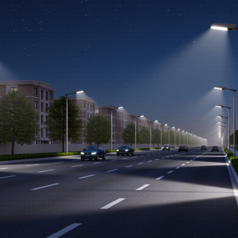
How to Meet Shielding Requirements for LED Street Lamps?
Define Shielding Requirements for LED Street Lamps
Shielding requirements begin with the site, not the luminaire. Record road width, mounting height, pole spacing, traffic speed, nearby homes, and pedestrian areas. These details define acceptable glare, uplight, and light trespass levels. A residential road may need stricter shielding than an industrial access route. Confirm the limits with the local lighting authority and applicable roadway standards.
Use photometric data to set measurable targets. Specify the maximum upward light output, glare rating, and illumination allowed beyond the property line. Full-cutoff optics can reduce skyglow, while house-side shields can protect bedroom windows. A visor may control forward glare, but it can also create dark patches on the pavement. That trade-off deserves a site calculation.
Check the installation, not only the drawing. Verify tilt angles, aiming, mounting height, and actual pole spacing after construction. Small angle changes can send bright light toward a second-floor window. Field measurements should compare pavement levels and vertical illuminance near sensitive properties. A design may appear compliant on paper yet fail at the boundary. That happens more often than expected. Reviewers should also question whether excessive shielding reduces uniformity, creates unsafe shadows, or increases energy use. Good requirements remain precise, practical, and open to correction.
| Requirement Area | Recommended Requirement | Practical Design Measure | Verification Method | Reference or Compliance Note |
|---|---|---|---|---|
| Upward Light | Prevent direct light from being emitted above the horizontal plane wherever the project specification requires zero or near-zero uplight. | Use a full-cutoff optical system, a flat or downward-facing lens, and a housing that blocks high-angle emission. | Review the photometric file and confirm the luminous intensity at vertical angles above 90° is zero or within the project limit. | The applicable limit is normally set by local outdoor-lighting regulations or the project specification. |
| Uplight Rating | Select the lowest practical uplight category for the site, especially near observatories, airports, protected areas, and dark-sky locations. | Specify a luminaire with a documented uplight classification and avoid installation tilt that redirects light above the horizontal plane. | Check the uplight component in the certified photometric report and recalculate it for the actual mounting angle. | The IES BUG system evaluates Backlight, Uplight, and Glare using zonal lumen data. The required rating depends on the site and lumen output. |
| Light Trespass | Limit illumination crossing property boundaries, entering windows, or reaching residential and environmentally sensitive areas. | Use house-side shielding, asymmetric optics, lower mounting angles, appropriate pole placement, and dimming during low-activity periods. | Measure or model vertical illuminance at the affected boundary and at representative window locations. | CIE 150 provides environmental-zone guidance for obtrusive light; local regulations may establish different limits. |
| CIE Environmental-Zone Control | Apply stricter shielding in darker environments and near conservation areas. | Classify the site as E0, E1, E2, E3, or E4 before selecting the optical distribution and aiming angle. | Compare upward light ratio, luminous intensity, and vertical illuminance against the selected environmental-zone limits. | CIE 150 commonly identifies E0 as intrinsically dark and E4 as a high-brightness urban environment. |
| Upward Light Ratio Reference | Use the project’s required maximum upward light ratio rather than assuming one universal value. | For guidance based on CIE 150, typical pre-curfew maximum values are 0% for E0 and E1, 5% for E2, 15% for E3, and 25% for E4. | Calculate the ratio from the complete luminaire photometric distribution, including any upward-emitting components. | Post-curfew values can be stricter. Confirm the edition of CIE 150 and the authority having jurisdiction. |
| Glare Control | Reduce high-angle luminance and direct view of bright LED sources for drivers, cyclists, pedestrians, and nearby residents. | Use a recessed LED board, diffuser or optic with controlled luminance, suitable shielding, and an appropriate distribution for the road geometry. | Review glare metrics, BUG glare classification, mounting height, aiming angle, and field-observed visibility of the LED source. | Glare limits vary by road class, traffic speed, pedestrian activity, and the applicable roadway-lighting standard. |
| Backlight Toward Properties | Control light emitted behind the pole, particularly beside homes, parks, hospitals, and other light-sensitive areas. | Choose a forward-throw distribution, install a rear shield when necessary, and orient the luminaire parallel to the road. | Inspect the backlight component in the photometric file and model illuminance on the property side of the installation. | Backlight is one of the three components of the IES BUG classification. |
| Mounting and Tilt | Install the luminaire at the designed tilt and avoid field adjustments that increase high-angle or upward emissions. | Use a level, adjustable slip-fitter or fixed bracket with an installation angle shown in the photometric design. | Record pole height, arm length, luminaire tilt, azimuth, and orientation during commissioning. | A luminaire that meets shielding requirements at 0° tilt may not meet them after upward tilting. |
| Optical Distribution | Match the beam pattern to the road width, pole spacing, lane arrangement, and required uniformity without excessive spill light. | Use roadway-specific asymmetric optics instead of relying only on lower wattage or physical shields. | Perform a point-by-point lighting calculation for average illuminance or luminance, uniformity, glare, and boundary spill. | Roadway lighting criteria should be taken from the applicable national or municipal design standard. |
| Dimming and Curfew Operation | Reduce light output when traffic and pedestrian activity decline, provided safety and security requirements remain satisfied. | Use scheduled dimming, adaptive controls, or motion-responsive controls with a defined minimum light level. | Verify programmed schedules, maintained light levels, control failure behavior, and post-curfew compliance. | CIE 150 distinguishes pre-curfew and post-curfew obtrusive-light limits in its guidance. |
| Photometric Documentation | Require a complete, traceable photometric file for the exact LED street-lamp configuration. | Specify the tested LED package, optic, driver setting, tilt, mounting height, and operating output. | Check the IES or EULUMDAT file, laboratory report, lumen output, candela distribution, and test conditions. | Photometric results must represent the installed product and operating condition, not only a similar model. |
| Final Site Inspection | Confirm that actual installation conditions match the approved shielding design. | Inspect shields, lens condition, pole alignment, tilt, aiming direction, control settings, and unintended light spill. | Use nighttime visual inspection, calibrated illuminance measurements, and as-built documentation. | Compliance should be confirmed against the approved design, local ordinance, and project acceptance criteria. |
Note: Shielding limits are jurisdiction-specific. The final LED street-lamp design should be checked against the current local lighting ordinance, roadway-lighting standard, environmental-zone requirements, and project photometric criteria.
Shielding keeps light on the pavement and limits rays toward windows, drivers, wildlife, and the night sky. Uncontrolled uplight creates sky glow. Small errors matter.
Review illuminance, uniformity, mounting height, tilt, glare, and property-line measurements together. A lamp may meet road targets yet disturb nearby bedrooms.
Choose optics that direct peak intensity onto the road, below the cutoff angle. Zero-uplight designs are useful where practical. Narrow beams may create dark gaps.
Add a visor, baffle, or house-side shield when optics cannot protect nearby windows. The shield should block high-angle rays without reducing useful road coverage.
A five-degree tilt can push light across a property boundary. Check the installed angle, not only the drawing. Drawings can be wrong.
Use a sealed, thermally stable housing with suitable ingress protection and corrosion resistance. Secure lenses, gaskets, and shields against dust, water, and vibration.
Test the lamp at its intended height, tilt, and operating setting. Measure uplight, backlight, glare, cutoff, uniformity, and average illuminance with calibrated equipment.
Yes. Map nighttime illuminance across a roadway grid and compare results with laboratory data. Wet pavement, trees, slopes, and dust can change real conditions.
Check normal, scheduled dimming, and emergency settings. Testing only the brightest mode is incomplete. The process is not perfect, but records reveal needed corrections.
Meeting the shielding requirements for LED street lamps begins with controlling where light is distributed, limiting glare, reducing unwanted upward illumination, and keeping light on the intended roadway. To understand what are the shielding requirements for led street lamps, designers should evaluate surrounding homes, wildlife areas, traffic conditions, and local lighting regulations. Appropriate optics, visors, internal shields, and carefully designed housings can shape the beam, minimize spill light, and support uniform illumination without excessive brightness.
Compliance should be confirmed through photometric testing, including measurements of light intensity, distribution, glare, and upward light. Installation also plays an important role: correct aiming, mounting height, tilt, spacing, and maintenance help preserve shielding performance over time. During upgrades, teams should reassess the optical system and verify that replacement components do not increase light trespass or reduce roadway visibility. A complete approach combines thoughtful design, objective testing, proper installation, and regular inspection to deliver efficient, comfortable, and well-controlled street lighting.

 Lijah Light